Text
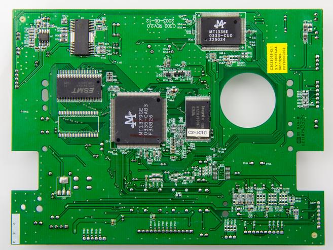
Take the printed circuit board as the mounting substrate, install electronic and electromechanical components, devices or other printed circuit board components on it, and use the printed circuit on the board ( It can also be made into passive electronic components such as resistance, capacitance, inductance, etc.) to realize electrical interconnection. In small electronic equipment, such as electronic watches, single-board microprocessors, and small semiconductor radios, all components and devices are mounted on a printed circuit board. And large-scale equipment (such as large-scale computer) is composed of dozens to thousands of printed circuit boards composed of plug-ins and corresponding printed circuit backplanes. Various printed circuit board components are shown in Figure 1. Each printed circuit board component is usually a functional unit. Early electronic equipment, electronic and electromechanical components, and devices were mounted on a chassis made of thin metal plates and used wires to achieve electrical interconnection. After the Second World War, with the development of printed circuit technology, electronic equipment, especially electronic computers, gradually formed a structural system based on printed circuit board components. Its advantages are good electrical performance, high reliability, small size, low cost, and automatic production. Printed circuit board components belong to the second and third level assembly (see electronic assembly level), and there are two assembly methods. ①Plane assembly or two-dimensional assembly: Components and devices are mounted on a plane (Figure 1), and printed circuit boards are used for interconnection. In order to improve the assembly density, components and devices can be mounted on both the front and back sides of the printed circuit board, or a metal plate can be sandwiched between the printed circuit board to improve the cooling capacity. ②Modular assembly or three-dimensional assembly: In order to increase assembly density, two printed circuit board components parallel to each other are generally used to form a space, and components and devices are installed in the space, or components are installed on the front and back sides of the printed board. Components and boards are interconnected by cables or connectors; it can also be like a bridge, where the legs of components and devices are respectively mounted on two printed circuit boards, called sandwich modules (Figure 2). The structural design of printed circuit board components must consider issues such as circuit division and standardization, assembly types, reasonable layout of components and devices, assembly structure, cooling methods, and mechanical dynamic characteristics. "Circuit division and standardization" are reasonably divided on the system block diagram, and the number of circuits and components and devices installed on a printed circuit board is specified. This is the circuit division. Simple electronic equipment does not have this problem, it can be solved with one or several printed circuit boards. However, in complex electronic equipment, such as large computers, the central processing unit alone has more than one hundred thousand components. Although large-scale integrated circuits have been used in the fourth-generation mainframe computers, the number of devices is generally several thousand. Therefore, selecting the optimal zoning scheme is a complicated design work. The design must first meet the requirements for electrical performance, including functionalization and testability, trace length and complexity, electromagnetic compatibility, fault location performance and maintainability. The second is the number of external leads and their optimization. Integrated circuits have developed to large-scale and ultra-large-scale integration, and the number of external leads of printed circuits has increased sharply, which severely limits the increase in assembly density and the full use of the potential of large-scale integrated circuits. Therefore, in the computer field, we should focus on the law of the gate-to-pin ratio (that is, the ratio of the number of circuits in a component or the number of gates to the external leads), and how to improve the gate-to-pin ratio. In addition, issues related to reliability, standardization, number of varieties, and assembly efficiency must also be considered.Assembly Type” Choose the assembly type according to the function, the number of components and devices, the assembly density, environmental requirements, cooling, the number of external connection leads, and the requirements of technology and materials. "Reasonable layout of components and devices" must meet electrical performance, process, heat dissipation and mechanical requirements.Assembly structure” According to needs, different additional structures are added to the printed circuit components, such as frameworks, stiffeners, various structural parts, panels, handles, plug-in accessories, shields and connectors. Cooling method Commonly used cooling methods include: natural cooling, forced ventilation cooling, liquid cooling, evaporative cooling and semiconductor refrigeration (see electronic equipment thermal control).Mechanical dynamic characteristics should be adapted to the requirements of work and transportation in the state of motion. In addition to the above requirements, man-machine connection and reliability issues must also be considered in the design.The assembly of printed circuit board components, from component and device preparation to component inspection, has been mechanized and automated. The equipment for assembly of printed circuit board components includes components, device aging and automatic detection and classification, components and device lead shaping, cleaning, immersion tin and other equipment, components and device automatic insertion machines (Figure 3), automatic and semi-automatic winding machines and various Kinds of automatic soldering equipment, etc. Electronic components and devices are generally plug-in installation. In order to increase the assembly density, directly use the chip or chip carrier to assemble.

