Definition
PSW flag definition:
PSW is an 8-bit binary register used to store the relevant CPU after the instruction is received The status is usually filled in by the CPU, but the user can also change the value of each status bit. The definition of each flag bit is as follows:
Bit7 Cy
Bit6 AC
Bit5 F0
Bit4 RS1
Bit3 RS0
Bit2 OV
Bit1 -
Bit0 P
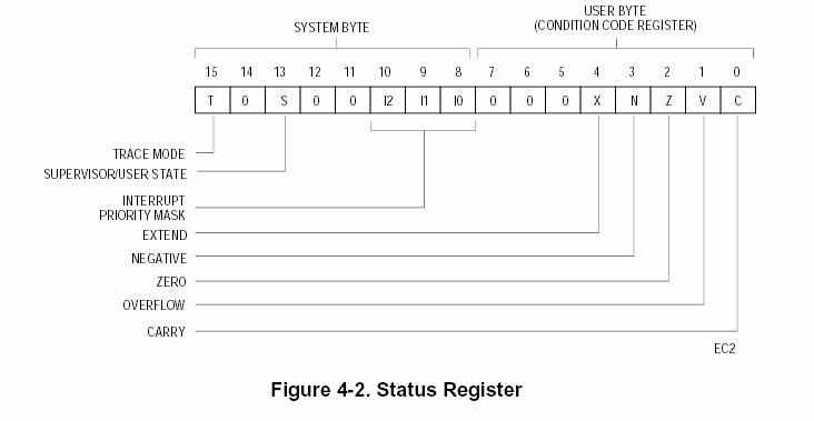
Program status register in ARM
There are 6 status registers in ARM, and the ARM7TDMI core contains 1 CPSR and 5 SPSRs for exception handlers. CPSR reflects the current state of the processor, which contains:

4 condition code flags (negative (N), zero (Z), carry (C) and overflow (V));
2 interrupt prohibition bits, respectively control one type of interrupt;
5 bits encoding the current processor mode;
1 used to indicate the current execution The bit of the instruction (ARM or Thumb).
Explanation of the PSW flags:
1. CY(Carry): Used to indicate the carry in the addition calculation and the borrow in the subtraction operation. There is a carry or in the addition operation. If there is a borrow in the subtraction operation, the CY position is 1, otherwise it is 0
2. AC(Auxiliary Carry): Basically the same as CY, the difference is the operation between the lower 4 bits and the upper 4 bits.
3.F0 (Flag Zero user flag bit): This bit is a flag bit set by the user according to his own needs. The user can determine the flow and branch of the program by setting this bit.
4. RS1, RS0: 8051 has 8 8-bit working registers R0~R7, and its actual physical location in RAM can be selected and determined according to needs. 00: 00H~07H
01: 08H~0FH
10: 10H~17H
11: 18H~1FH
5. OV: Indicates whether an overflow occurred during the operation. If the result exceeds the range of data that can be represented by an 8-bit binary number, that is, a signed number -128~+127, the flag is set to 1.
6.OP: The parity flag is used to indicate the parity of the number of 1s in the operation result. If P=0, the number of 1s in the accumulator A is even; if P=1, Then the number of 1 in accumulator A is odd.
